Summary
Nucleus motorized microscopes from Zaber form a compact benchtop microscope platform that offers a flexible configuration to adapt the user needs, and includes fast and precise motorized XY and Z-focus movement devices. Nucleus microscopes are fully controlled by the Inscoper I.S. control and image acquisition solution, allowing users to benefit from its combination with a complete and easy-to-use imaging software.
We show in this technical note how fast is the Zaber X-ADR XY stage of the Nucleus microscope compared to a regular one.
ZABER PRODUCTS
Zaber (Vancouver, BC, Canada) designs and manufactures positioning devices such as linear or rotational stages, optical mounts, micromanipulators, stepper motors which are used in different industries, including microscopy and life science.
Zaber products also include the Nucleus modular automated microscope platform which includes both upright and inverted microscopes. They are designed to be compact, customized and affordable.
In this note we focus on the Nucleus platform but it is worth noting that all devices from Zaber can be easily integrated in the I.S. solution thanks to convenient software tools (device library, communication protocols).
NUCLEUS motorized microscope for 5D fluorescence imaging
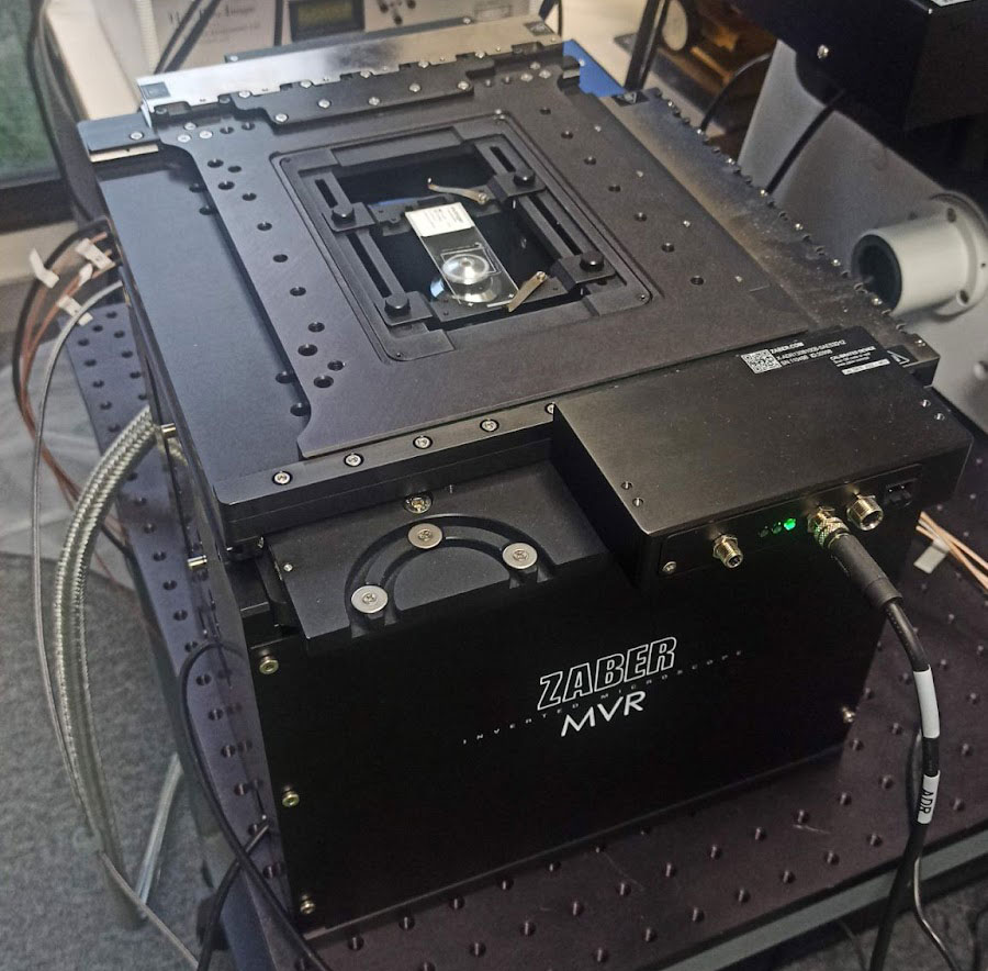
Zaber Nucleus microscopes are compact (Figure 1), and suitable to be used in a laboratory environment or a microscopy imaging core facility. They include a motorized XY stage and a motorized Z-focus, white light for bright field illumination, three LED illumination sources and 6 filter positions for fluorescence imaging. Up to two C-mount camera ports are available, for maximum compatibility with cameras available on the market. The objective holders are compatible with optics from all four manufacturers (Evident, Leica, Nikon, Zeiss).
Nucleus microscope have a flexible configuration: they can be adapted or customized to user needs and applications such as BrightField, Epifluorescence or multi-well plate screening.
Figure 1: Zaber Nucleus inverted microscope
Integration and performance tests with Inscoper I.S.
INSCOPER (Cesson-Sévigné, France) develops software solutions for device control and image acquisition in microscopy. Its main product I.S. is compatible with all camera-based microscope setups and dedicated to a large panel of applications such as live cell imaging, confocal imaging, ratiometric imaging, light-sheet microscopy, super-resolution, photomanipulation (FRAP) or FLIM imaging.
I.S. offers a user-friendly graphical user interface (Figure 2) allowing the full control and combination of all motorized devices, multidimensional acquisitions (time, XYZ, channels, multi-positions, tiling) and image visualization. It consists of one window with three tabs (Configuration, Acquisition, Visualization) and has been designed to address all kinds of needs in microscopy acquisition with the aim to always keep a simple and intuitive user exprience.
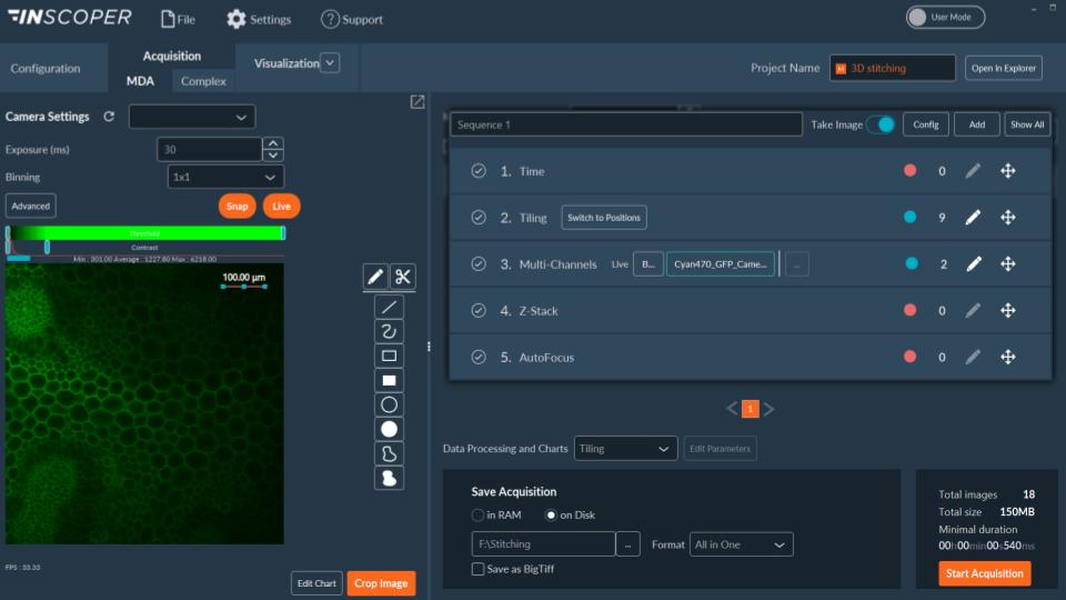
Figure 2: user-friendly interface, Acquisition tab with multidimensional acquisition model
You can watch on this demo video how easy it is to navigate in the I.S. software environment to configure and acquire images with a Zaber Nucleus microscope.
Test conditions
A special feature of the I.S imaging solution is that it is based on a technology that eliminates all software latency when communicating with the microscope devices to control. This feature allows users to benefit from 2x to 4x higher frame rate for their acquisitions. But it is also particularly useful when testing motorized devices such as stages, because we are certain to compare their strict hardware performance with no impact or variation caused by software drivers or the computer’s operating system.
Another essential feature for technical analysis is that I.S. generates a “performance file” associated with each acquisition. The duration of each command for each device is recorded down to the microsecond, enabling a very detailed and precise study of acquisition performance.
For this technical note we performed two sets of tests:
- We compared the performance of a Zaber Nucleus X-ADR stage with a standard stage (Nikon Ti2) in acquiring a tiled imaging,
- We simulated maximum stages performance for moving from one point to another randomly in X and Y directions.
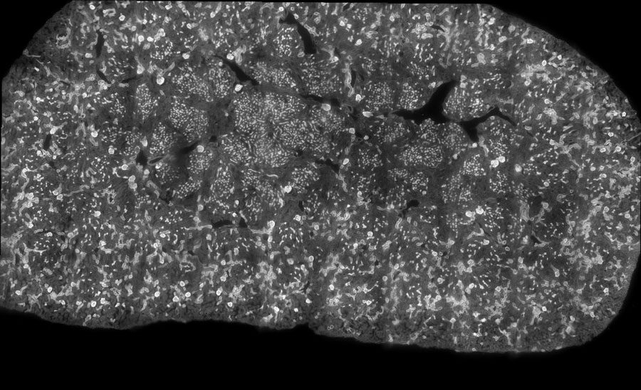
Figure 3: Tiling imaging of Mouse kidney (60 tiles) acquired with a Nucleus microscope (Zaber) using a Zeiss 20x objective. The same acquisition was performed with a standard microscope (Nikon Ti2). Label is WGA 488 nm, GFP filter has 466/48 nm excitation and 525/49nm emission.
XY scanning speed when acquiring a tiled image
In this first set of tests, we performed a tile imaging experiment of mouse kidney with a 20x objective (Figure 3). The acquisition sequence was exactly the same for each microscope, Zaber Nucleus and Ti2: 60 tiles with 10 rows and 6 columns set in fastest “snake” mode (first row acquired from left to right, then second row from right to left, etc.). Exposure time was 30 milliseconds.
Thanks to the performance file, the precise scanning speed for the tiling acquisition for each system is recorded for each movement at the microsecond. Results are shown in Table I: the average XY scanning speed, including the exposure time, was 4.3 mm²/s for the MVR and 1.2 mm²/s for the Ti2. The XY scanning speed of the Nucleus microscope was 3.5 times faster in average than the Ti2 for this tile imaging experiment. This XY “surface” speed does not discriminate between the X and Y axis, what we will do next.
| Nikon Ti2E | Zaber Nucleus | |
| Sample support | Slide | Slide |
| Number of tile images | 60 (10 x 6) | 60 (10 x 6) |
| Exposure time | 30 ms | 30 ms |
| Average XY scanning speed | 1.2 mm²/s | 4.3 mm²/s |
Table I: Scanning speed comparison between Zaber Nucleus and Nikon Ti2 microscopes for the same image acquisition sequence
Maximum XY scanning speed
In this second set of tests, we compared the time taken to move each stage from one position to another as quickly as possible.
To ensure greater measurement reliability and equal test conditions between the two stages, we used an internal software tool that generates random X,Y coordinates within a defined maximum range. Ninety-nine (99) random positions were generated within a motion range of 0 to 25 mm.
The maximum speed of the standard stage tends towards 21 mm/s for X and Y axes, which corresponds to Nikon specifications (approx. 25 mm/s).
The maximum speed of the Zaber X-ADR stage reaches 160 mm/s in the Y axis and 100 mm/s in the X axis at the longest travel distance tested, with no clear convergence to a maximum value.
We know from Zaber that the difference between both axes is due to the additional mass of the lower axis (X), and that the default maximum speed for this stage is 250 mm/s. This value could be reached with longer distances than those performed in this test. It can be increased up to 750 mm/s, but Zaber warns that it will also increase the acceleration (dv/dt) which may be problematic for the well being of some samples, and can also generate some vibrations that would increase the settling time.
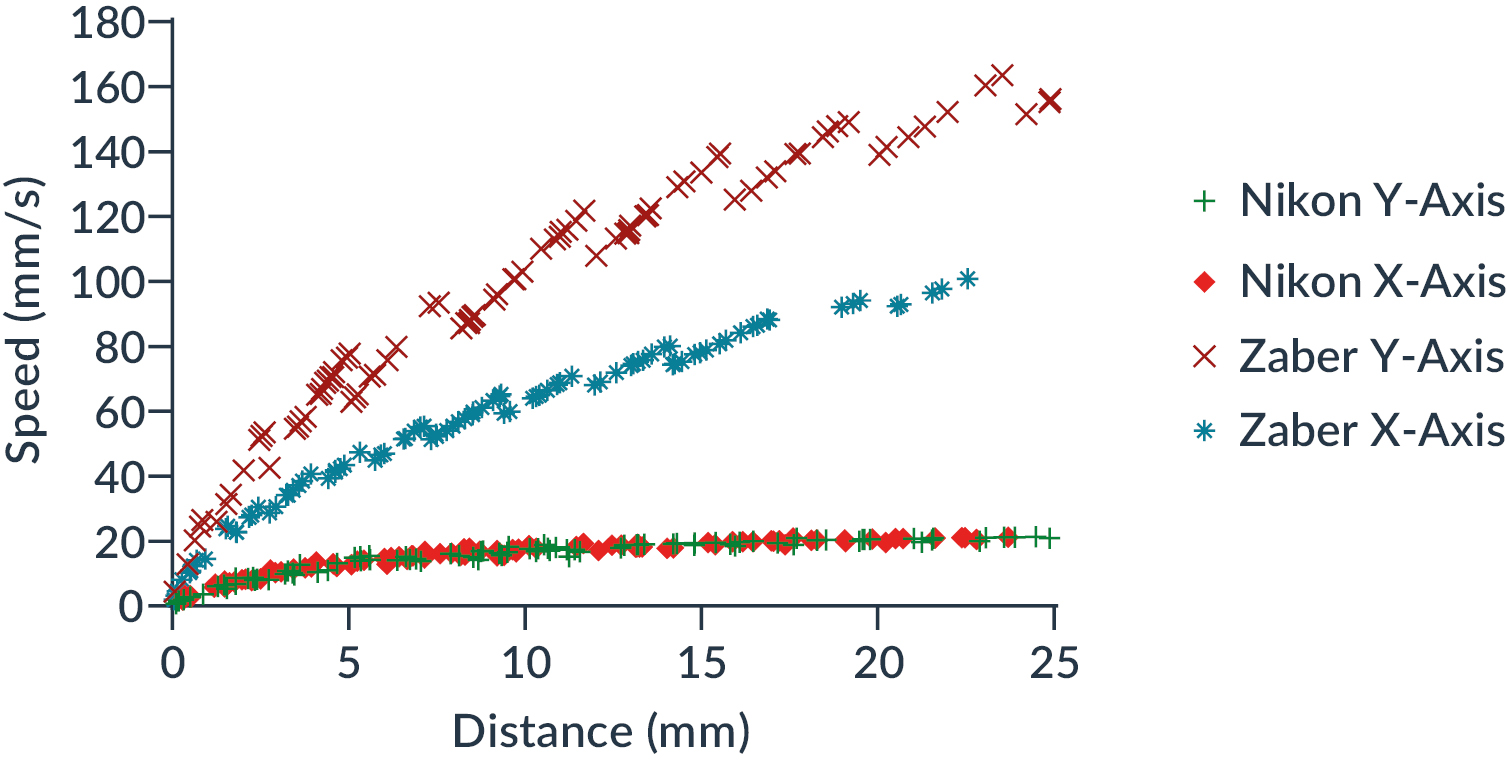
Figure 4: Comparison of X-axis and Y-axis movement speed between Zaber and Nikon stages as a function of distance traveled
Then, we extracted the polynomial function of each speed curve from the Figure 4 to calculate the theoretical ratio between the two systems (Zaber/Nikon) and for each axis.
Results are shown in Figure 5. We note the systematic and significant outperformance of the Zaber stage compared to the reference stage, whatever the distance to be covered.
Both curves have a minimum around 2 to 2.5 mm travel distance, corresponding to an outperformance factor of 3x for the X axis and 5x for the Y axis. Depending on the distance, the Zaber stage moves at least 3 times faster on the X axis, with a maximum of 5 times at 25 mm, and at least 5 times faster on the Y axis, with a maximum of 9.8 times for 0.25 mm.
We found no positioning problems or precision errors during our tests. Please remember that these values were obtained using the I.S. imaging solution which adds no software latency to the hardware time required for movement.
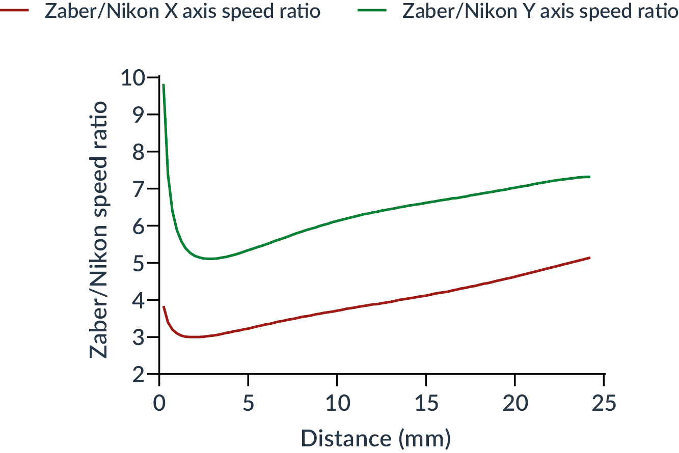
Figure 5: Ratio as a function of the distance traveled between the speed of Zaber and Nikon stages for each axis (X in red, Y on green)
0 Comments